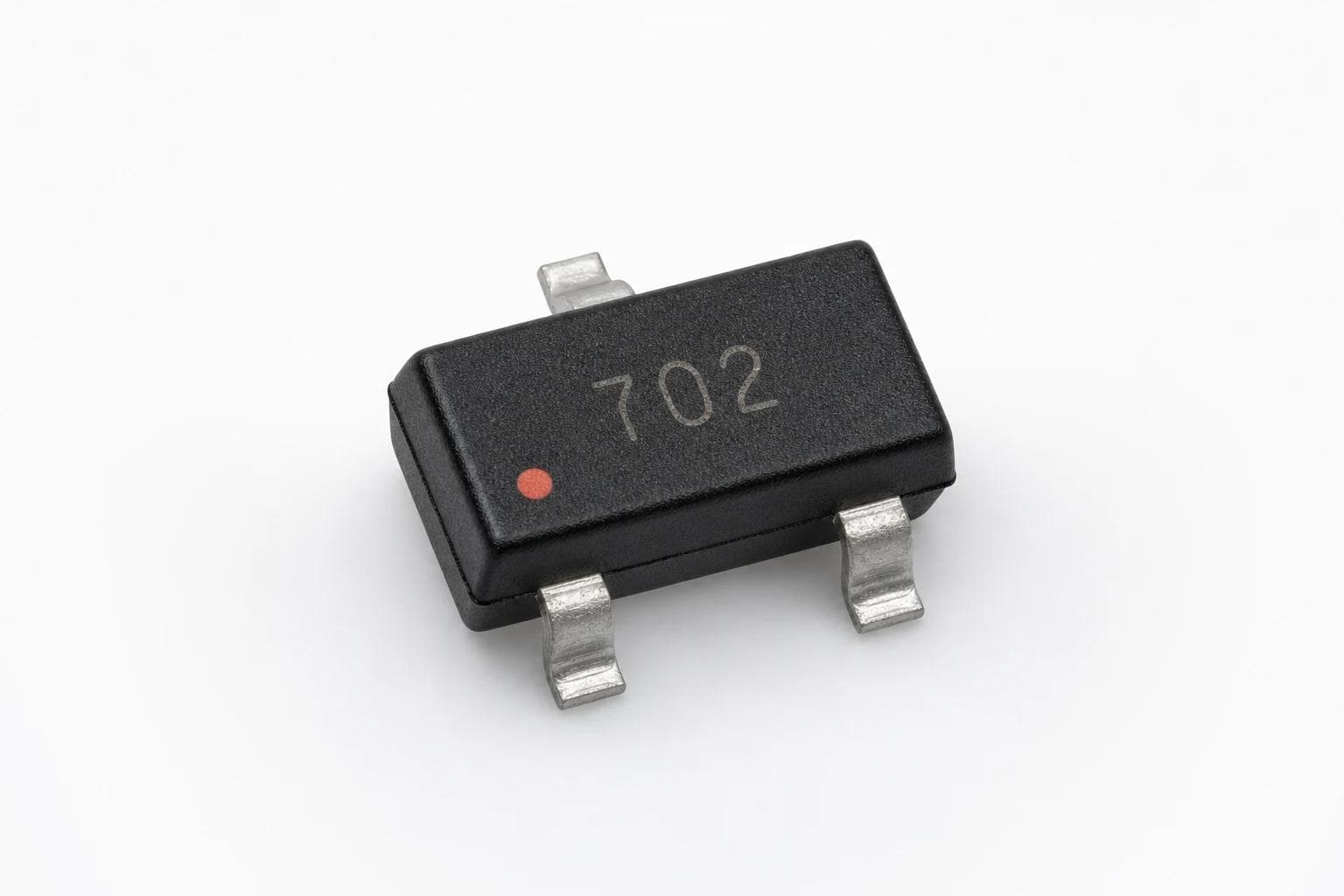
An automotive interface may face handling discharge, cable events, electrical transients, and a wide operating-temperature range. Protection selection therefore begins with the interface and its exposure path rather than a single peak ESD number.
Define the protected signal window
The protection device must remain inactive during normal signaling while clamping abnormal events early enough to protect the downstream circuit. Working voltage, breakdown behavior, clamping performance, and capacitance must be reviewed together.
| Input | Why it matters |
|---|---|
| Signal / bus type | Sets voltage range, bandwidth, and capacitance sensitivity |
| Connector exposure | Defines likely discharge and cable-coupled events |
| Downstream withstand | Determines required clamping performance |
| Temperature range | Changes leakage and protection behavior |
| Qualification target | Connects the component to program-level requirements |
Verify signal integrity and fault behavior
For high-speed or sensitive interfaces, validate insertion loss and waveform quality in the actual layout. Also review short-to-battery, reverse bias, repetitive pulses, and any system-specific surge requirement.
Component qualification is important, but system compliance depends on the complete protection network, PCB layout, grounding, connector construction, and test method.